Architecture:Map Module
The map module for v0.4 is still in active development, so the section below is incomplete and in part refers to the v0.3 map engine. However, chances are that a new implementation will work in a similar fashion. For more details regarding the ongoing development refer to the Mapengine and Mapview tasks.
Map Objects and Shapes
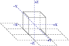
On the outside, Adonthell is a 2D game, where the world consists entirely of 2D sprites as provided by the Gfx Module. These, together with position information, are hereafter referred to as map objects. Internally, for the purpose of collision detection, the extend of map objects is represented by a simple 3D model, called its shape. Object model data is persisted into an XML file. The coordinate system used by shapes is as follows:

The camera position is fixed and provides for a top-down view on the map. It follows that the X axis in 3D space runs from west to east, the Y axis from north to south and the Z axis from bottom to top. Due to the top-down view, there is no visual distinction between Y and Z axis. It is not possible to view the sides of an object, only its front and top part. (Note that the image above diverts from that view for clarity.)
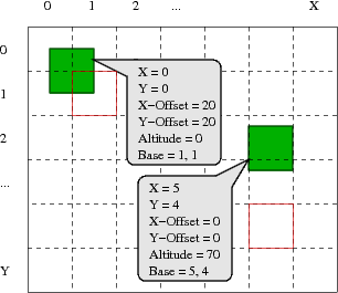
The map itself is assembled from map objects, not from the underlying shapes. It consists of a grid (currently using cells of 40 by 40 pixels), where the map objects can be placed. By default, the top-left corner of a map object (i.e. sprite) is aligned to the top-left corner of the cell it is placed on. To allow more flexibility in placement of map objects, an offset can be specified. However, for non-flat sprites (i.e. walls or characters), the sprite is offset by the height of its underlying shape.
All cells occupied by a map object hold a reference to that object, but one of them is special. The cell that contains the bottom-right corner of the map object is called the base of that object. It is important during the rendering phase, when the grid is traversed from left to right and top to bottom. For each cell, only those objects are drawn (according to their z-order) for which this cell is their base.

The example above shows two flat sprites (i.e. ground tiles) placed on the map grid. The first is sitting on the ground, but it is offset and thus spans multiple cells. The cell containing its bottom-right part is its base (marked by a red border). The second tile is floating at an altitude of 70px, but only occupies a single cell. Due to the top-down point of view, impression of altitude can only be achieved through sprites that are drawn to give that impression. No 3D techniques like shading or projecting shadows are employed by the engine, as the shapes have little part in the actual rendering.
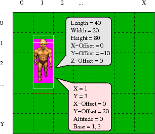
Similar to static objects, the position of moving entities, such as creatures or NPCs, is kept in terms of cell-coordinates, offset from the cells' corner and current altitude. As a shape does hold no reference to the map object it belongs to, it does have no knowledge of its absolute position in the world. All it knows is its size (represented by a bounding box) and a relative position to the sprite, as shown below:

From all the above follows that the position of a map object on the screen (in pixels) is determined as follows
 x_px = X-Coordinate * GRID_SIZE + X-Offset
 y_px = Y-Coordinate * GRID_SIZE + Y-Offset - Altitude - Shape-Height
Collision Detection
The collision detection is implemented using the swept sphere algorithm described in [1]. Details regarding the algorithm can be found there. What remains to be described here is the coordinate-transformation that needs to take place in order to map absolute (pixel-)coordinates of moveable map objects to the relative coordinates of the shapes we test for collision.
To be explained later ...
Maps and Views
One prominent component of the engine is the renderer. It produces the graphical representation of a scene, and that about 40 times per second. (A new scene – or internal engine state – is computed about 75 times per second, btw.)
More important than those numbers or the fact that drawing and update operations are disjunct is the implementation. As the heading suggests, a model-view-controller (MVC) architecture is used.

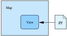
The part of the map being displayed is determined by so-called mapviews. A mapview can be of any size and can direct output to any surface. Multiple mapviews can be active at the same time, although at present they can’t show different maps, just different areas of the same map.
The question that remains is how a mapview knows what part of a map to display. For that purpose, each mapview may have a schedule script assigned (the controller), which is executed before rendering takes place. The script in turn can use the methods provided by the mapview class for all kinds of effects. Usually, it will want to center the view on a certain character, but it is not limited to this.
Map Events
The engine itself implements only the rendering of the map. Everything else, like transitions between map areas (characters entering buildings for example), interaction with items or characters on the map (picking up, initiating dialogue) and interaction with the map itself (traps, falling down) are handled by Python scripts. To trigger these scripts, so called map events are implemented and registered with the Event system.
The following events were implemented in the v0.3 engine and will probably appear in v0.4 as well:
- An enter event is triggered when a character enters a location (tile)
- A leave event is triggered when a character leaves a location (tile)
- An action event is triggered when the player interacts with characters or objects on the map